PROTOTYPE 2
"The spatial logic needs to be immediately readable, not something learned through trial and error."
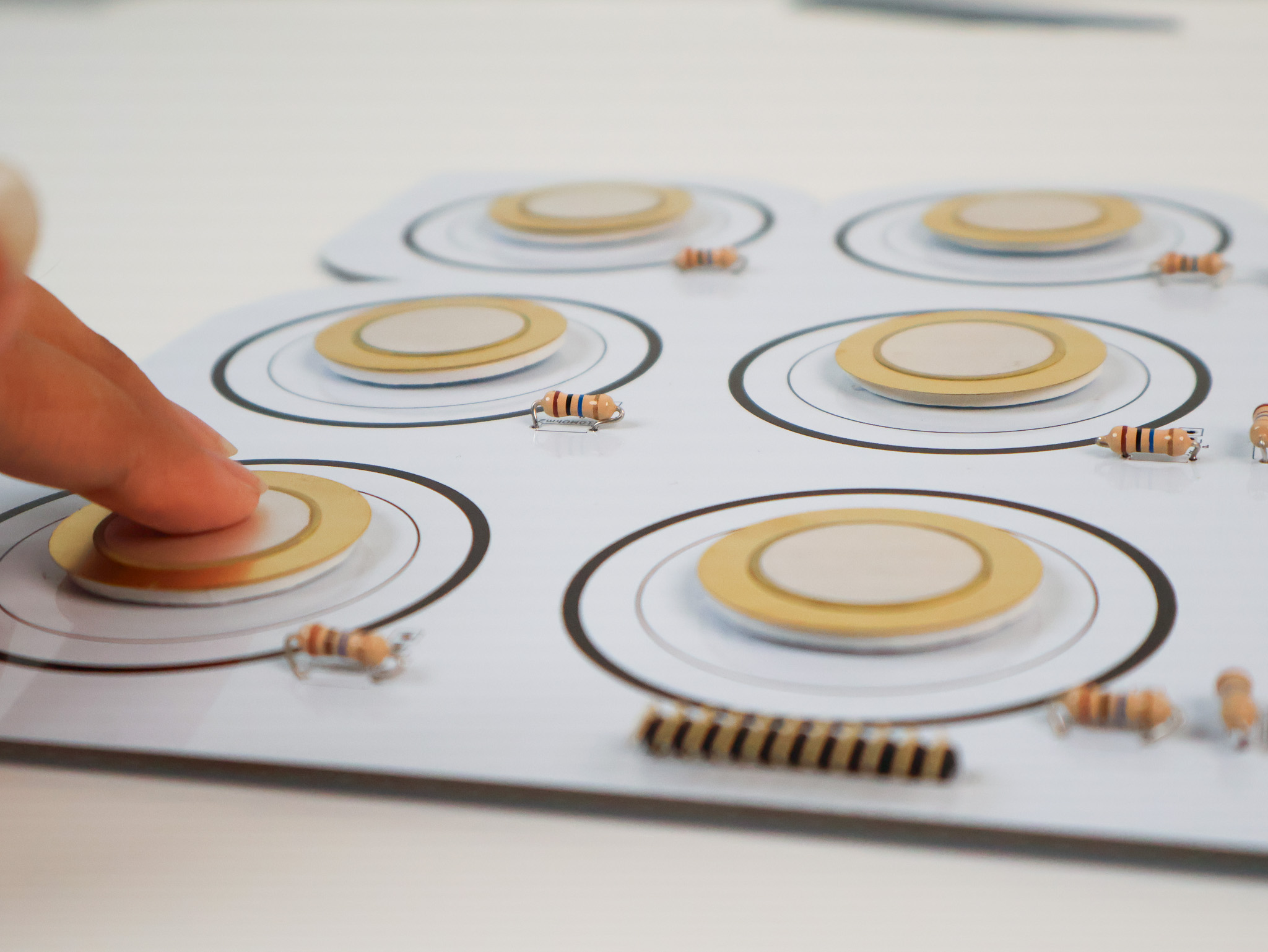
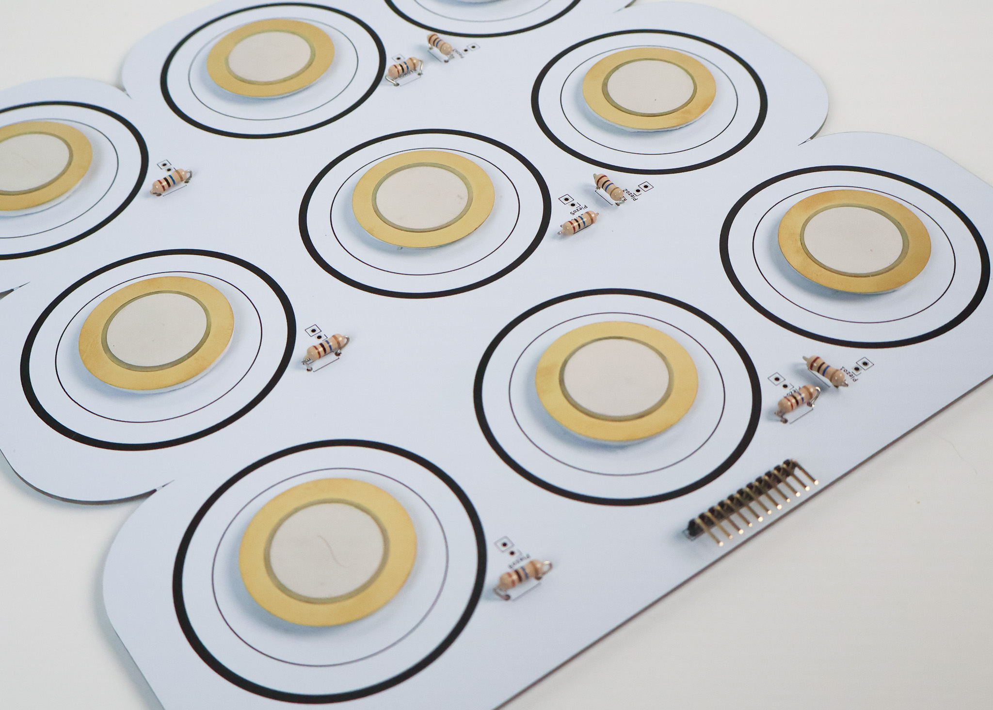
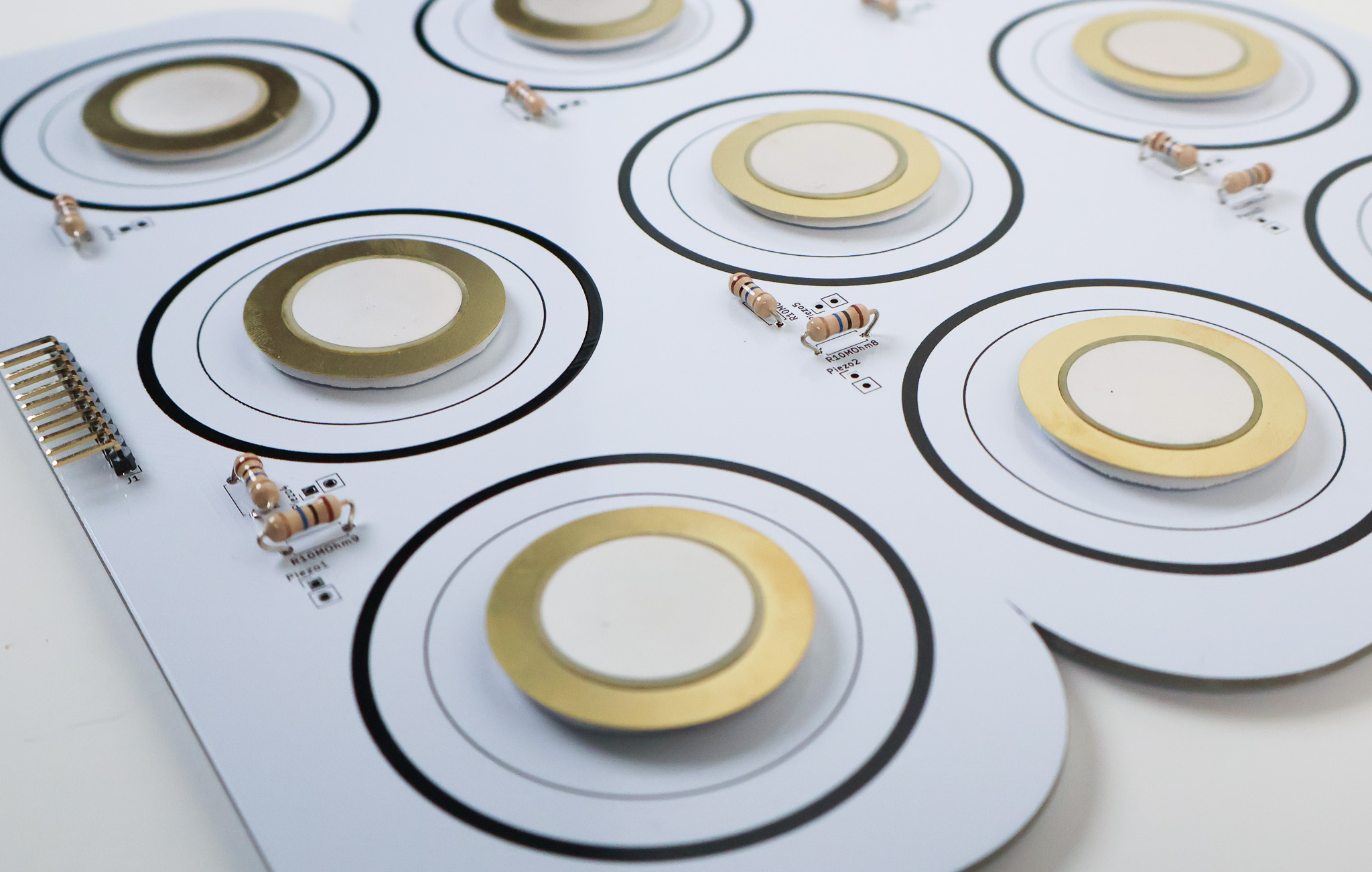
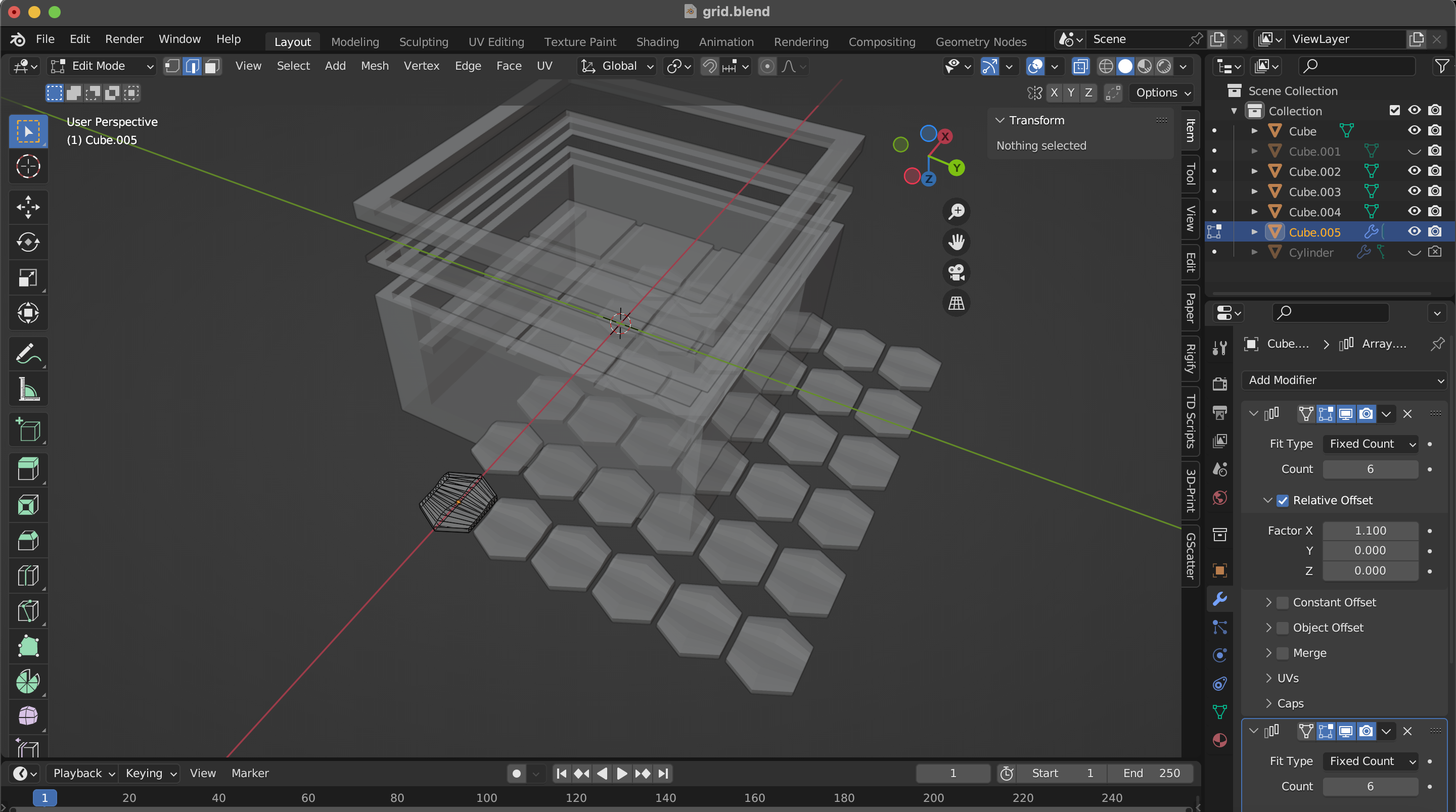
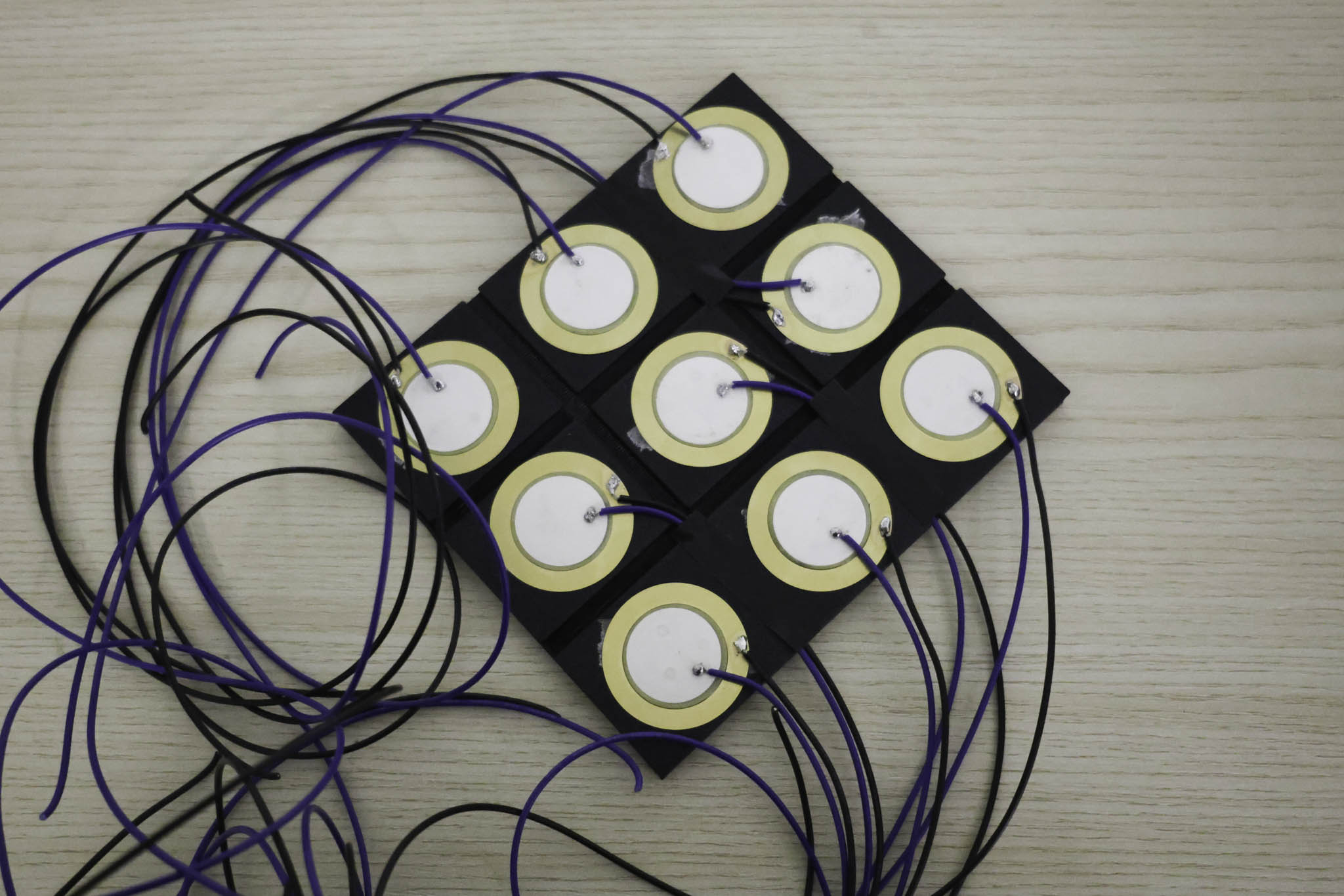
From bars to zones: Prototype 1 used a linear layout, each sensor a horizontal strip. Prototype 2 rethought this as a 3×3 grid, so that position itself becomes part of the expressive vocabulary. A strike in the top-left corner means something different from one in the centre.
The enclosure combines laser-cut wood with 3D printed sensor mounts. Wood adds warmth and weight, the kind of material quality that reads as intentional. The 3D print gives precise geometry where the form needs it. Together they continue the idea that material texture is a design variable the performer notices and responds to.
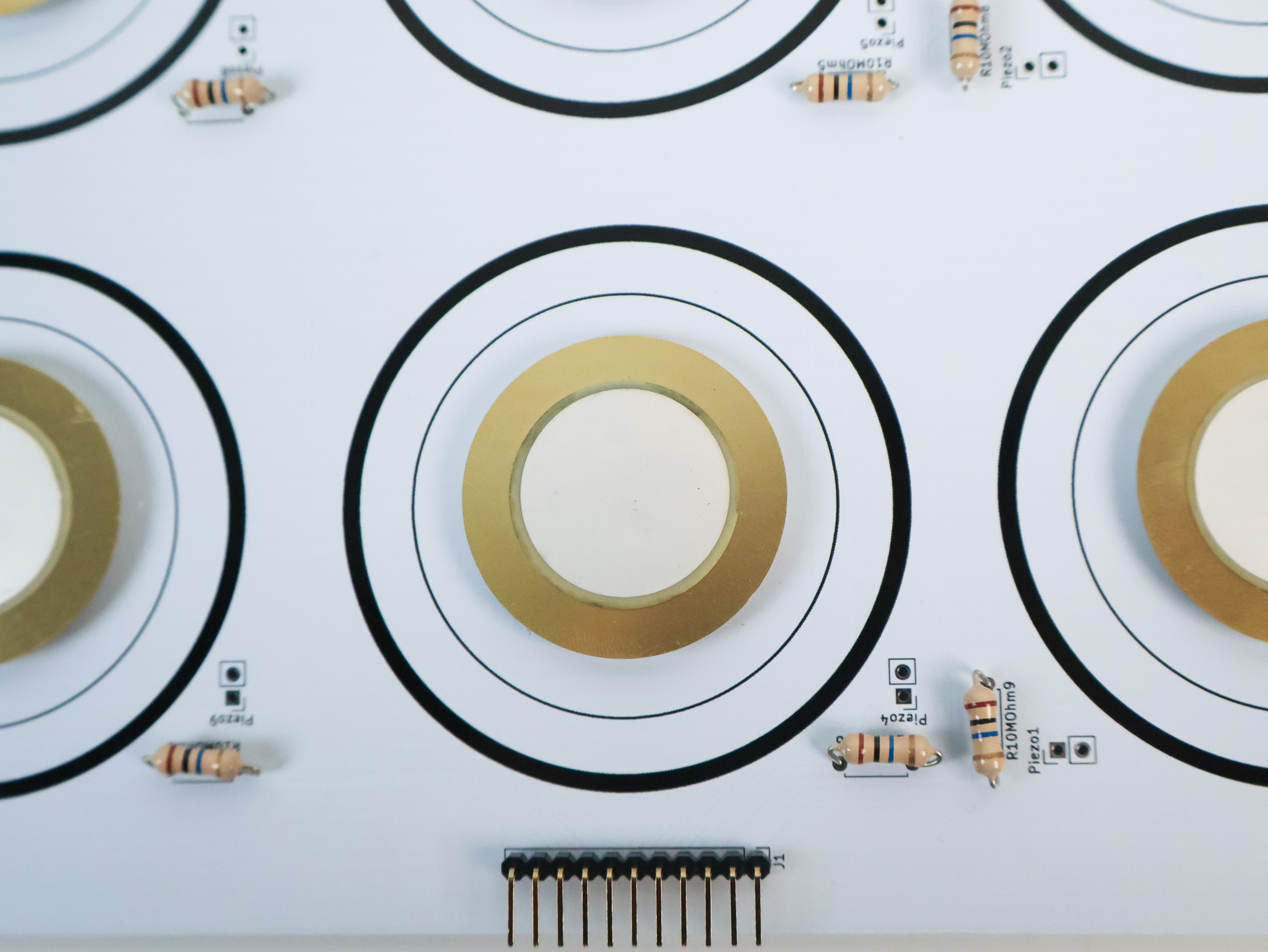
Nine sensors, nine channels. The Arduino UNO only has six analog inputs, so this prototype moved to an Arduino Mega. A prototyping shield sourced from Kuriosity at Sim Lim Square sits directly on top, providing cleanly labelled breakout pins. All sensor connections were soldered to both sides of the shield, keeping the wiring structural rather than improvised.
The 3×3 sensor grid maps spatially to a 3×3 visual grid in p5.js. Each zone responds independently, the top-right sensor activates the top-right visual region. The spatial correspondence is what makes the controller feel legible: the feedback mirrors the physical action directly.
Prototype in Use
| Participant | Q1 | Q2 | Q3 | Q4 | Q5 | Q6 | Q7 | Q8 | Q9 | Q10 | SUS Score |
|---|